PCB Generator
The PCB Generator creates KiCad project files from your keyboard layout. It generates a key matrix schematic, places switch and diode footprints according to key positions, and can optionally route connections between components.
Overview
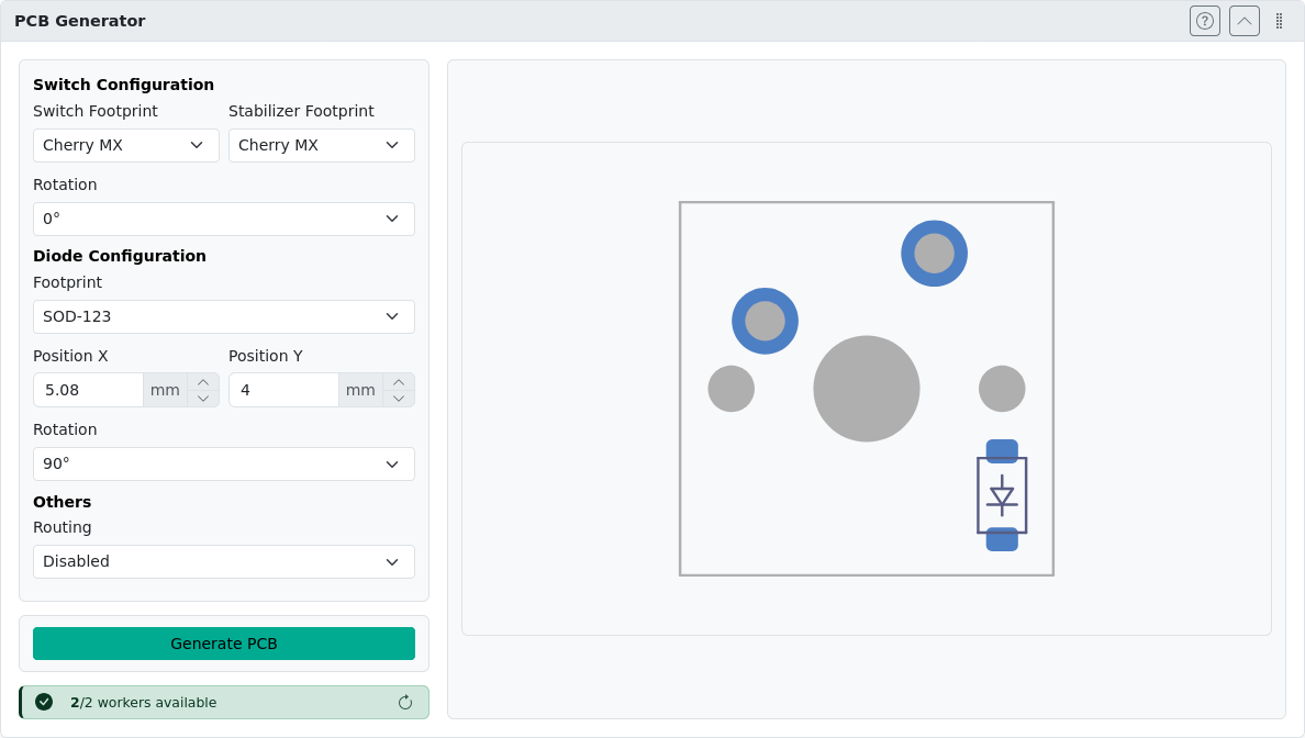
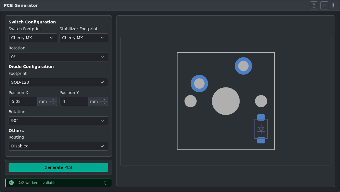
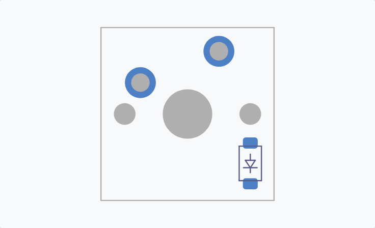
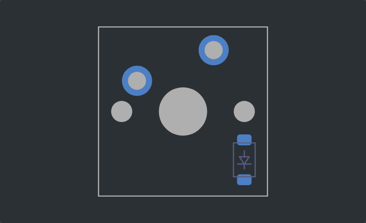
Open the PCB Generator panel. The panel displays a footprint preview and generation controls. After project generation the footprint preview is replaced with preview of the resulting schematic and PCB file.
Prerequisites
Before generating a PCB, your layout must have:
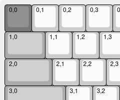
- Matrix coordinates — Each key must have row/column assignments in VIA label format (e.g.,
0,0for row 0, column 0). Use Add Switch Matrix Coordinates if not already set. - Maximum 150 keys — Layouts with more than 150 keys are not supported.
Matrix coordinates determine how switches are wired in the keyboard matrix.
Matrix Coordinates
Matrix coordinates in kle-ng use VIA label format. Each key's top-left label contains the row and column assignment as row,col (e.g., 0,0, 0,1, 1,0).
The easiest way to assign matrix coordinates is to use Add Switch Matrix Coordinates, which can annotate your layout automatically or let you draw rows and columns manually.
Generating a PCB
- Verify your layout has matrix coordinates assigned
- Open the PCB Generator panel
- Configure switch, diode, and routing options as needed
- Use the preview window to check key-diode placement
- Click Generate PCB
- Wait for the server to process your layout
- Once complete, preview renders will be displayed
- Click Download ZIP to save the archive, or New Task to start over
WARNING
The preview does not support displaying traces for Routing option enabled.
Automatic Routing Limitations
The automatic router attempts to connect switches to diodes using a basic algorithm that finds the shortest path with 45° angles. Important limitations:
- Incomplete routing — The router may leave connections unrouted if it encounters layout obstacles. It does not try alternative paths; it simply skips difficult connections.
- DRC required — Always run KiCad's Design Rule Check after generation to identify unrouted nets.
- Manual finishing needed — The generated PCB is a starting point and requires manual review and completion in KiCad.
After Downloading the PCB
The downloaded ZIP archive contains two files:
.kicad_sch— Schematic with the switch matrix.kicad_pcb— Board file with switch footprints placed according to key positions and matrix coordinates, diode footprints for each switch, routed connections (if routing was enabled)
Extract the ZIP and open the .kicad_pcb file in KiCad 9+ to continue PCB design.
Next Steps in KiCad
Typical next steps after downloading:
- Add a microcontroller — Place your MCU footprint (e.g., Pro Micro, RP2040) and connect row/column lines.
- Add a USB connector — Route the data lines from the MCU to the connector.
- Add mounting holes — Use the footprint library to place M2 or M3 standoff holes.
- Add the edge cut — Generator does not include PCB outline; create it to match your intended case.
- Run DRC — Use KiCad's Design Rule Check to catch errors before sending to fabrication.
Tips and Best Practices
Download and Service Limits
- Download expiration — Generated PCB files expire after 1 hour.
- Rate limiting — There is a 5-second cooldown between generation requests.
- Worker status — The PCB generator runs on a remote worker. If the service is temporarily unavailable, try again later.
KiCad Compatibility
Generated files are compatible with KiCad 9+. Open the file in KiCad to add mounting holes, USB connector, microcontroller, and other components.
Troubleshooting
Missing VIA JSON Export
"Download VIA JSON" option is missing — This is a separate export from Import & Export. For PCB generation, you only need matrix coordinates on the keys, not a full VIA metadata block.
Missing Keys in Output
Keys are missing from the generated PCB — Only keys with valid matrix coordinates (row,col in the top-left label) are included. Use Add Switch Matrix Coordinates to assign coordinates to all keys, then verify none are missing.
Service Unavailability
The PCB worker is unavailable — The generator uses a remote server. If requests fail, try again after a few minutes. Your layout data is not lost — regenerate from the same layout.
Privacy note
This feature sends your layout data to a backend server for processing. Generated files are stored for 1 hour and then automatically deleted. No data is used for any other purposes.