Plate Generator
The Plate Generator creates switch and stabilizer cutouts for your keyboard layout, exporting to SVG, DXF, STL, and JSCAD formats for manufacturing processes like laser cutting or 3D printing.
WARNING
The Plate Generator does not prevent usage of settings which are not manufacturable in practice. Always validate your settings against your intended manufacturing method.
Overview
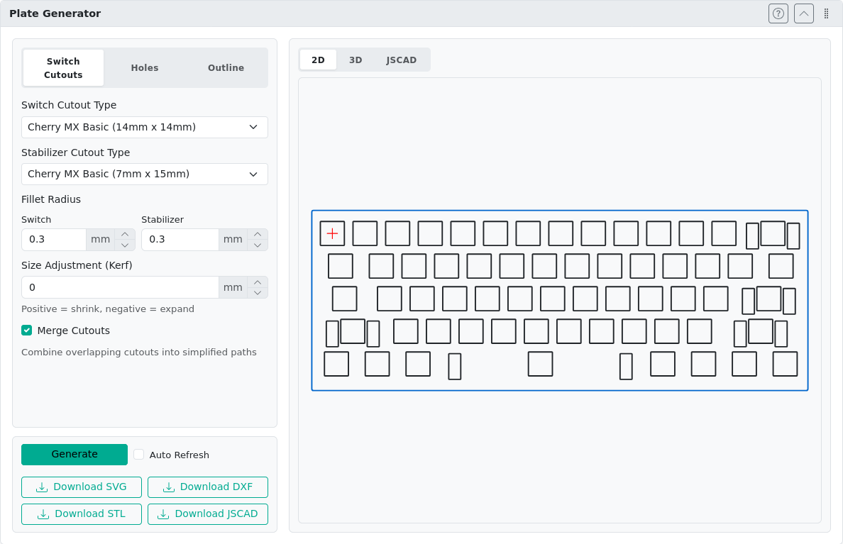
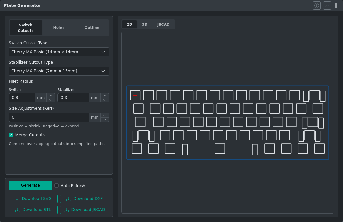
Open the Plate Generator panel. The settings section is organized into five tabs:
- Switch Cutouts — Select switch type, stabilizer style, fillet radius, and kerf compensation
- Holes — Add corner mounting holes or custom holes at arbitrary positions
- Outline — Generate a border around the key cluster
- 3D — Plate thickness, backside features for 3D export
- JSON — Edit, download, and upload plate settings as JSON for scripting and sharing configurations
Typical Workflow
- Complete your key layout design in the canvas editor.
- Open the Plate Generator panel.
- On the Switch Cutouts tab, select the switch type and any stabilizer options for your layout.
- On the Outline tab, choose an outline type and set your margins.
- If you need mounting holes, configure them on the Holes tab.
- If exporting to STL or JSCAD, configure the 3D tab: set plate thickness and enable any backside features as needed.
- Review the live preview. The preview updates automatically as you change settings.
- Click Download to export in your preferred format (SVG or DXF for laser cutting; STL or JSCAD for 3D printing).
TIP
If specific keys need a different switch or stabilizer orientation (e.g., rotated stabilizers on a split spacebar), set the Switch orientation or Stabilizer orientation per key in the Key Properties panel before generating. See Manufacturing Properties for details.
Switch Cutouts
Configure the shape and size of switch cutouts.
Supported Switch Types
- Cherry MX
- Alps
- Kailh Choc
Fillet Radius
Rounds the corners of cutouts. Useful for CNC routing where sharp internal corners are not achievable. Note: the upper limit for fillet values is dictated by geometry, not by actual application constraints.
Size Adjustment (Kerf)
Kerf is the total width of material removed by the cutting tool (e.g., the laser beam). The cutout path shrinks by half the kerf value on each side so the final physical hole matches the intended size.
Example: A 14mm cutout with kerf 0.5mm is drawn at 13.5mm. The laser removes 0.25mm per side, resulting in a 14mm hole.
This is an advanced option and can often be left at 0. Negative values expand cutouts, which is useful for small adjustments in 3D printing.
Merging Cutouts
Combines overlapping shapes into single paths. Useful when stabilizer cutouts overlap with switch cutouts.
Per-Key Orientation
To adjust the orientation of individual switch or stabilizer cutouts, set the Switch orientation or Stabilizer orientation property in the Key Properties panel. See Manufacturing Properties for details.
Holes
Corner Mounting Holes
Places holes at each corner of the plate at a specified distance from the edge. Requires outline generation to be enabled.
Custom Holes
Add holes at arbitrary positions using keyboard units (U). The reference position (0,0) is marked with a red cross in the preview.
Outline
Generate a border around the key cluster.
Outline Types
| Type | Description |
|---|---|
| None | No outline generated |
| Rectangular | Axis-aligned bounding box with independent top/bottom/left/right margins |
| Tight | A convex hull that encloses the key cluster, expanded by a single uniform margin |
The Tight outline is useful for non-rectangular layouts or split keyboards. Ghost keys (keys with the Ghost property enabled) are included in the hull calculation without producing switch cutouts — place them at the edges of the layout to fine-tune the outline shape.
Configuring the Outline
| Setting | Description |
|---|---|
| Margin / Margins | Distance from cutout bounds to outline edge (switch and stabilizer cutouts are considered; holes are not) |
| Fillet Radius | Rounds corners of the outline |
| Merge with Cutouts | Place cutouts and outline in a single file; if separate, the outline file shares the same (0,0) origin for easier CAD/CAM handling |
3D Settings
Configure plate thickness and backside features for 3D export formats (STL, JSCAD). All 3D tab controls are disabled when outline is set to None.
Plate Thickness
Thickness of the plate in millimeters. This value is used in STL and JSCAD exports. Maximum practical thickness depends on your intended manufacturing method and backside feature depths.
Backside Features
Cut Depth
Sets the depth in millimeters of all backside cuts from the back face. This applies to all enabled backside features and stabilizer clearance pockets. The maximum value is thickness − 1 mm. Set to 0 to disable all backside cuts (useful for thin plates, e.g. 1–1.5 mm, where backside features are not needed).
Cherry MX Snap Notch
When enabled, a 7 mm × 17 mm rectangular notch centered on each switch cutout is subtracted from the back face of the plate. This allows Cherry MX switches to snap into a thick plate for mechanical retention. This feature is 3D-only and does not appear in SVG or DXF output.
Stabilizer Clearance Pockets
When Cut Depth is greater than 0, the generator automatically cuts stabilizer clearance pockets on the back face. These require no configuration and are generated regardless of whether any named backside feature (e.g. Snap Notch) is enabled. The pocket shape depends on the stabilizer type. Stabilizer clearances are 3D-only and do not affect SVG or DXF output.
WARNING
Alps stabilizer backside clearances have not been validated. Verify the pocket geometry against your actual stabilizer hardware before manufacturing.
3D Preview
The 3D preview displays a rendered view of the plate geometry. The bottom-right corner contains controls for visualization:
- Solid — Renders the plate as a solid mesh (default view)
- Wireframe — Renders the plate in wireframe mode, useful for inspecting internal geometry and backside features
- Reset view — Button to reset the camera to the auto-fit position
The camera position is preserved across plate regenerations. Click Reset view to return to the default auto-fit view after panning or rotating.
JSON Settings
The JSON tab provides direct access to plate settings as formatted JSON. This is useful for power users who want to:
- Edit multiple settings at once
- Share or version-control configurations as files
- Build or modify settings programmatically
Using the JSON Editor
The JSON editor displays the current settings in real-time. Use it to:
- Edit settings directly — Modify values and click Apply (or press Ctrl+Enter) to apply changes to the preview
- Reset — Discard unsaved edits and revert to the last applied settings
- Download — Save the current settings as a
plate-settings.jsonfile - Upload — Load a previously saved
plate-settings.jsonfile. If valid JSON is provided, it applies immediately; if there are syntax errors, the editor loads the file so you can fix it - Resize — Drag the handle below the editor to adjust its height
The status bar at the bottom shows:
In syncwhen the editor matches applied settingsModified — press Apply or Ctrl+Enter to applywhen unsaved changes exist- Error or warning messages if the JSON is invalid
JSON Format
All sections and fields are optional — omitted fields fall back to defaults. Here is a representative example showing all available sections:
{
  "cutout": {
    "switchType": "cherry-mx-basic",
    "stabilizerType": "mx-basic",
    "switchFilletRadius": 0.5,
    "stabilizerFilletRadius": 0.5,
    "kerf": 0,
    "merge": false
  },
  "holes": {
    "mounting": {
      "diameter": 3,
      "edgeDistance": 3
    },
    "custom": [{ "diameter": 3, "offsetX": 0, "offsetY": 0 }]
  },
  "outline": {
    "outlineType": "rectangular",
    "marginTop": 5,
    "marginBottom": 5,
    "marginLeft": 5,
    "marginRight": 5,
    "filletRadius": 1,
    "mergeWithCutouts": true
  },
  "thickness": 1.5,
  "threed": {
    "backsideFeatures": [{ "type": "cherry-mx-snap-notch" }],
    "backsideDepth": 1.2
  }
}
Switch types: "cherry-mx-basic", "cherry-mx-openable", "alps-skcm", "alps-skcp", "kailh-choc-cpg1350", "kailh-choc-cpg1232", "custom-rectangle" (for custom-rectangle, add "width" and "height" fields inside cutout)
Stabilizer types: "mx-basic", "mx-bidirectional", "mx-tight", "mx-spec", "mx-spec-narrow", "none"
Outline types: "none" (no outline), "rectangular" (axis-aligned with independent margins), "tight" (convex hull with single margin — use "tightMargin" instead of the four directional margins)
Presence rules:
holes.mountingpresent implies corner mounting holes are enabledholes.custompresent implies custom holes are enabledstabilizerFilletRadiusis omitted whenstabilizerTypeis"none"threedsection is omitted when no backside features are enabled andbacksideDepthis0(both default)
3D section fields:
backsideFeatures— Array of enabled 3D features. Presence in the array means enabled. Currently supported types:"cherry-mx-snap-notch"backsideDepth— Shared cut depth in millimeters for all backside features and stabilizer clearance pockets. Set to0(default) to disable all backside cuts
JSCAD Format
The exported JSCAD file uses OpenJSCAD v2 format. Open it in the online viewer at openjscad.xyz.
After generating a plate, the JSCAD script is shown in the results area. The script preview editor includes an expand button in its bottom-right corner. Click it to open the full script in a read-only modal dialog — useful for inspecting longer scripts or copying the script text.
Using Ghost Keys to Shape the Outline
The Ghost key property (in the Key Properties panel) marks a key as invisible — it is included in outline hull calculations but produces no switch cutout. This lets you control the outline shape in ways that the key cluster alone cannot:
- Extend the outline past the edge of the cluster (place a ghost key outside the normal key area)
- Protect clearance for a USB connector or encoder by placing a ghost key in that space
- Smooth corners on an irregular layout by placing ghost keys at extremes of the hull
Ghost keys appear as faint transparent rectangles on the canvas so they remain visible while editing.
| Without ghost keys | With ghost keys |
|---|---|
Layout 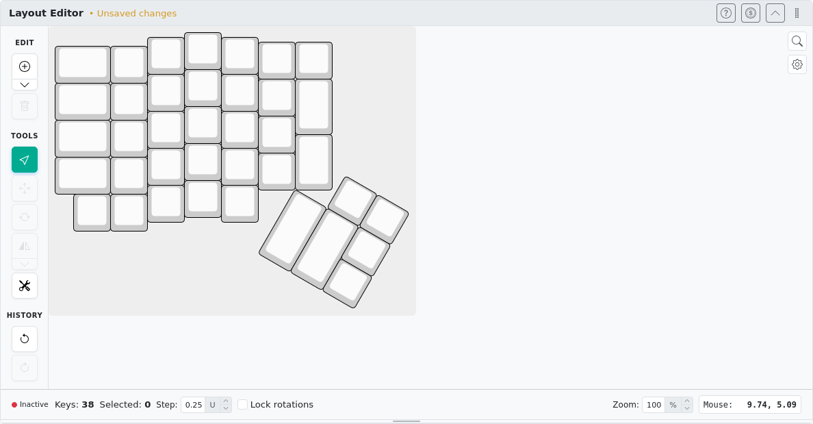  | Layout 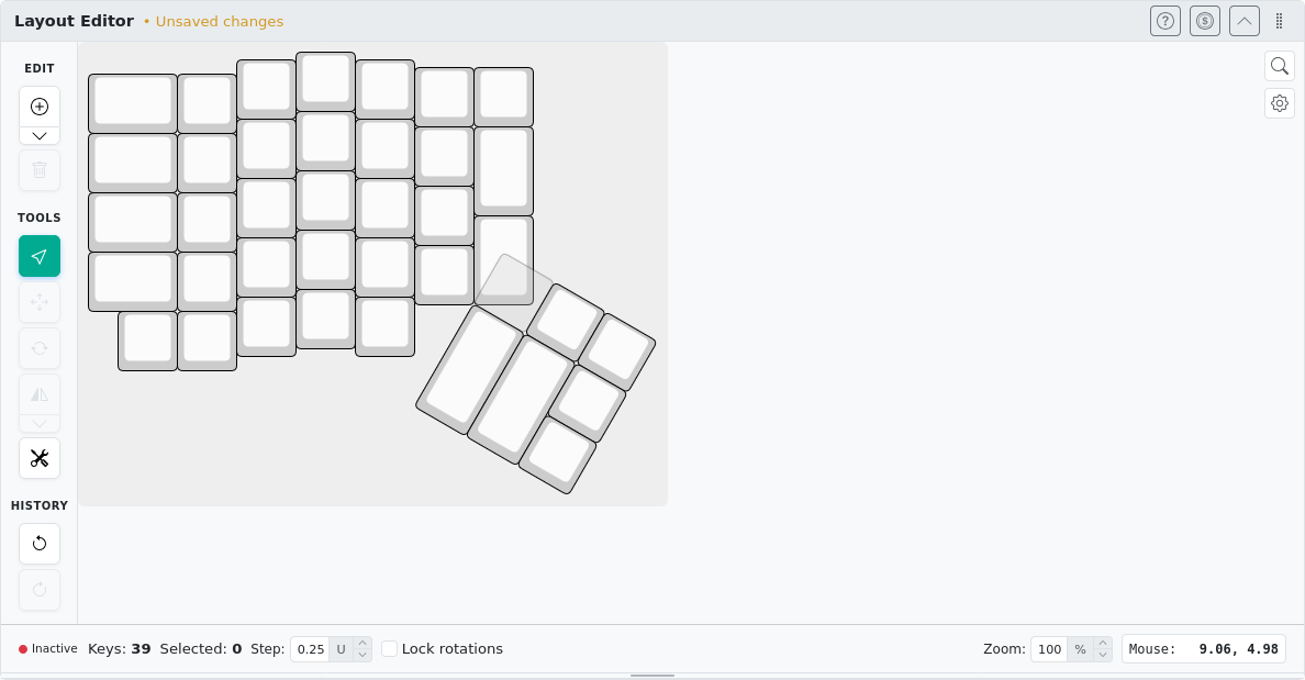 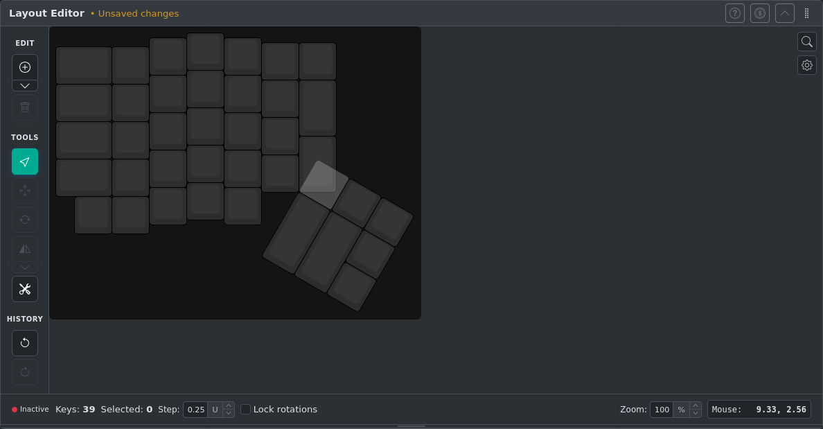 |
Output 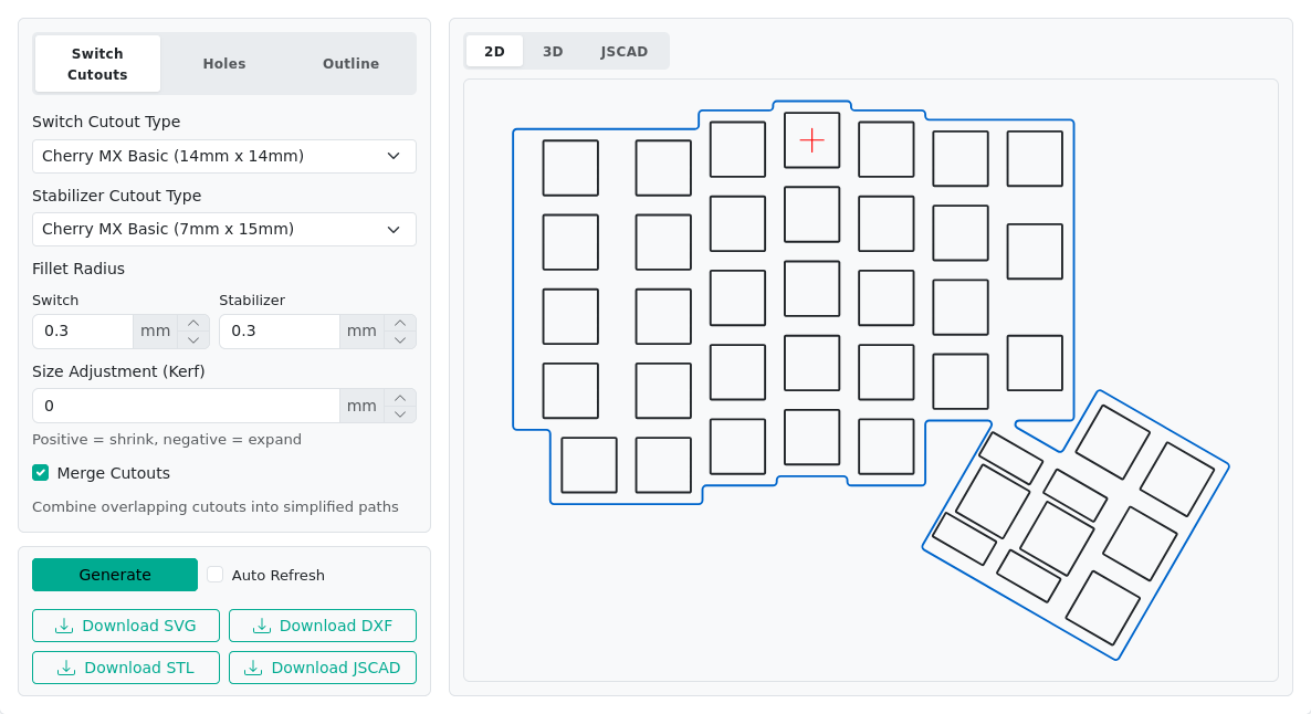 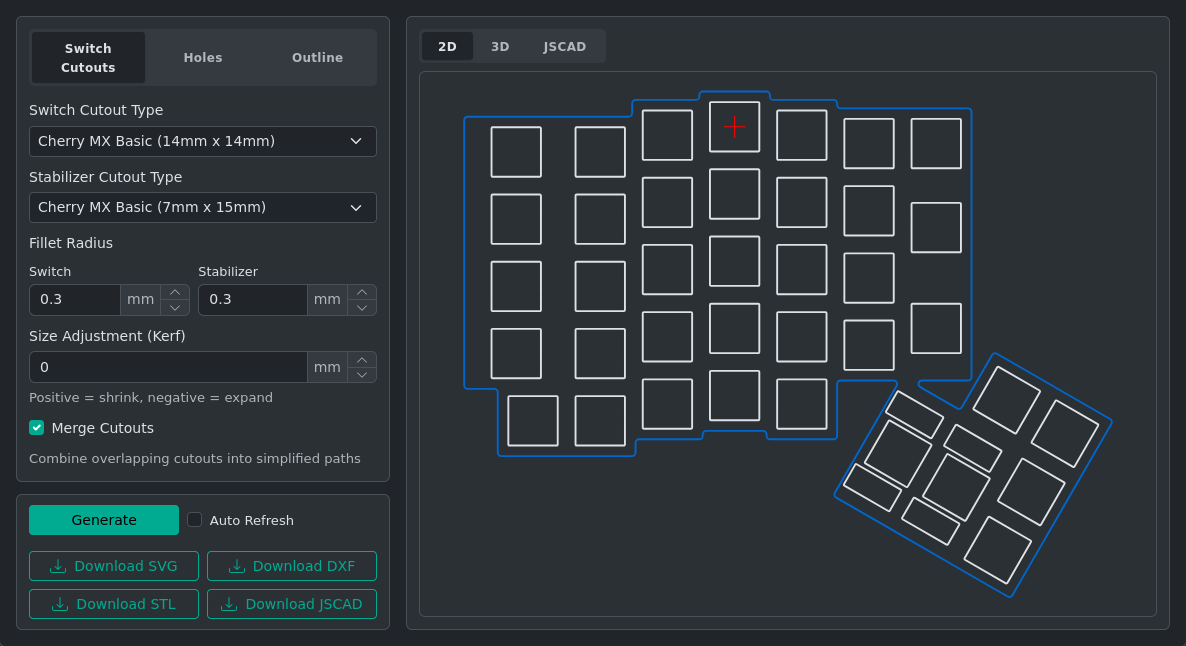 | Output 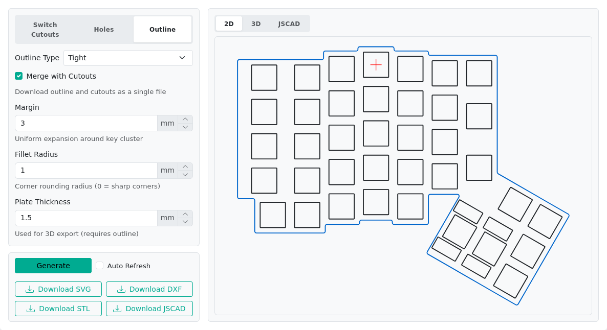 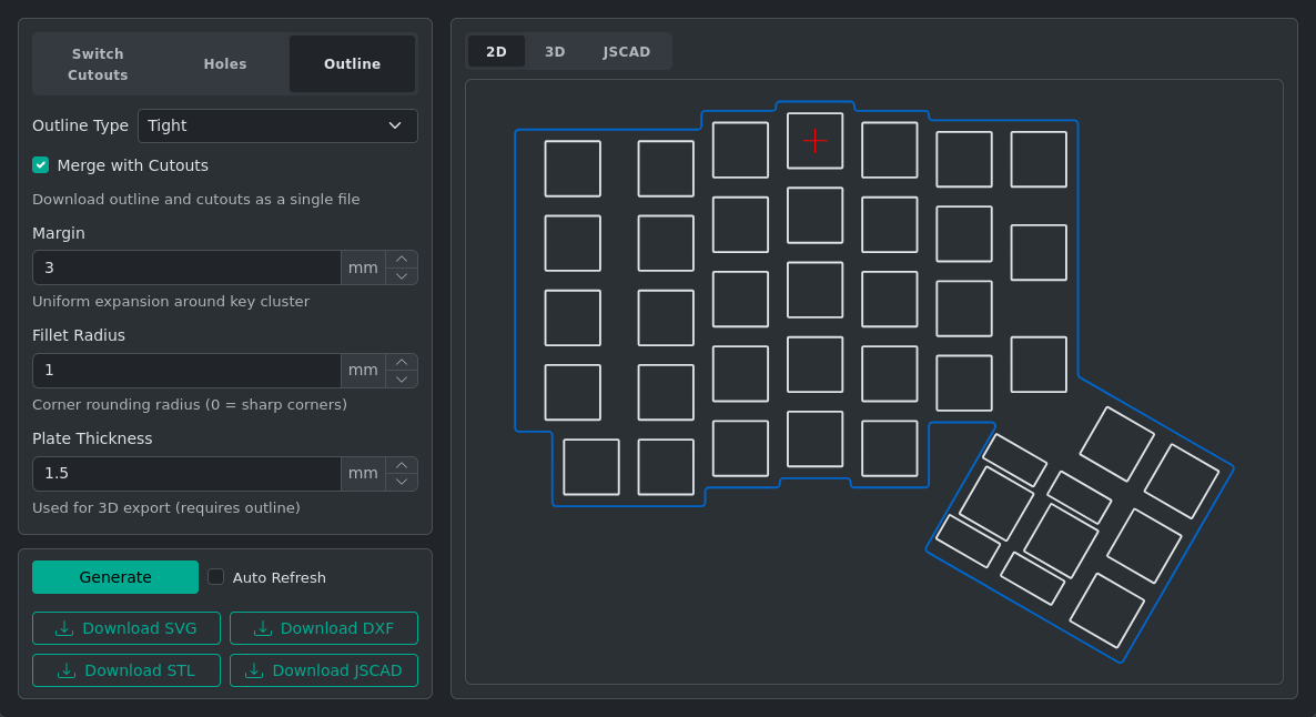 |
Troubleshooting
Cutouts at Wrong Positions
Cutouts appear at wrong positions — Verify that your layout uses the correct mm/U spacing in Keyboard Metadata. Cherry MX standard is 19.05 mm/U. Kailh Choc is 18 mm/U. A mismatch here causes cutouts to be placed at wrong physical distances.
Stabilizer Orientation Issues
Stabilizer cutout is the wrong orientation — Set the Stabilizer orientation on individual keys in Key Properties. Values must be a multiple of 90°. See Manufacturing Properties for guidance.
Outline Coverage
Outline doesn't wrap closely enough — Switch to the Tight outline type. Use ghost keys to extend coverage to areas the key cluster doesn't reach.
Kerf Settings
Kerf value to use — 0 is correct for many laser cutters where you want to program exact dimensions. Ask your cutting service for the actual kerf (typically 0.1–0.5 mm for laser cutting). Use negative kerf to expand cutouts (sometimes useful for FDM 3D printing where plastic shrinks slightly).
Credits
Based on ai03 Plate Generator and swillkb Plate & Case Builder.